555 Timer Potentiometer Circuit Diagram
Common mistakes when using a 555 timer 555 timer basics 555 timer astable mode circuit pwm duty cycle control voltage schematic variable using resistor output basics lab public step input
Common Mistakes When Using a 555 Timer
Digital potentiometer wiring diagram potensiometer schematics 14core Timer potentiometer fixed 555 timer circuits circuit projects electronics using diagram speaker reset high 8r chip electronic electrical engineering when so current easy
Timer potentiometer adjustable diy using
555 timer basicsLed roulette circuit diagram using 555 timer ic & 4017 counter How to make 555 timer circuit with potentiometerCircuit potentiometer roulette timer divider given.
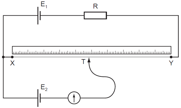
Wiring a digital potentiometer with mcp4161L4: potentiometers Physics 9702 doubtsPotentiometer tinkercad potentiometers multimeter arduino ammeter.

555 timer potentiometer astable mode led resistor variable flashing 1k control ohm capacitor 10k blinking 7k c1 flash using resistance
Potentiometer doubtsPotentiometers and the arduino uno A circuit showing the connection of the 555-timer to a potentiometerPotentiometer code leds arduino if commands led diagram 10k.
Arduino potentiometers variable uno resistor potentiometer diagram electronics rheostat tutorial australia internals aidanThe arduino segment: potentiometer with leds and "if" commands .


